Hexbeam wire size & type
1. Wire gauge

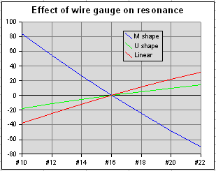
Wire gauge has only a minor impact on the Forward Gain or F/B performance of a Hexbeam; however, it can have a significant effect on the tuning and the SWR. The chart on the right illustrates why.
Here we see the shift in resonant frequency caused by changing the wire-gauge on three differently-shaped 20m dipoles: the M-shape used for Classic Drivers, Classic Reflectors and Broadband Drivers; the more-open U-shape used on Broadband Hexbeam Reflectors; and, for reference, a linear dipole. The shifts are referenced to the resonant frequency we get by using #16 wire.
We see that the resonant frequency of the linear dipole increases by about 70KHz as we decrease the wire diameter from #10 gauge to #22 gauge. This is an expected result - "fatter" dipoles normally need to be a bit shorter for the same resonant frequency. However the M-shape dipole is quite different - its resonant frequency falls by 154KHz for the same decrease in wire thickness!
I have explored this characteristic by modeling "bent dipoles" with various included angles and noted the effect of changing the wire gauge. As a linear dipole is gradually bent into the M-shape, the change in wire gauge has less and less effect until, with an included angle of 90 degrees, it has no effect at all. When the dipole is bent further to included angles less than 90 degrees, the effect re-appears but in the opposite sense! I have seen no explanation of this in the technical literature. My guess (no more than that) is that at an included angle of about 90 degrees the decreased inductance of a thicker wire is offset by increased capacitive coupling between the two halves of the dipole. At smaller included angles, the capacitive effect predominates, and at larger angles the inductive effect predominates.
We see from the chart that the U-shape dipole is relatively immune to wire gauge changes - its resonant frequency increases by only 33KHz for the same decrease in wire diameter.
So what does all this mean for the Hexbeam constructor? Well, it appears we can safely ignore the effect of wire gauge on U-shape Broadband Hexbeam Reflectors; however we need to take it into account when arriving at dimensions for M-shape Classic Hexbeam Drivers and Reflectors, and Broadband Hexbeam Drivers.
What happens if we don't bother to correct for wire gauge? On a Broadband Hexbeam the resonance of the Driver will shift relative to the resonance of the Reflector; because this will affect only the VSWR - not the tuning - it is probably OK to use #14 or #18 wire without making any corrections to the #16 wire dimensions. On a Classic Hexbeam, both Driver and Reflector resonances will shift by roughly the same amount, resulting in a mis-tuned antenna but with little change to the SWR.
So then, what corrections do we need to make for the wire gauge? If we assume a linear relationship between wire gauge and frequency we shall not be far out. This leads to the following handy set of "correction factors" for adjusting dimensions that have been quoted for #16 gauge wire:
| Band | #22 | #20 | #18 | #16 | #14 | #12 | #10 |
| 20m | - 1.3" | - 0.9" | - 0.4" | 0 | + 0.4" | + 0.9" | + 1.3" |
| 17m | - 1.0" | - 0.7" | - 0.3" | 0 | + 0.3" | + 0.7" | + 1.0" |
| 15m | - 0.9" | - 0.6" | - 0.3" | 0 | + 0.3" | + 0.6" | + 0.9" |
| 12m | - 0.7" | - 0.5" | - 0.2" | 0 | + 0.2" | + 0.5" | + 0.7" |
| 10m | - 0.7" | - 0.4" | - 0.2" | 0 | + 0.2" | + 0.4" | + 0.7" |
- # 22 multiply by 0.994
- # 20 multiply by 0.996
- # 18 multiply by 0.998
- # 16 multiply by 1
- # 14 multiply by 1.002
- # 12 multiply by 1.004
- # 10 multiply by 1.006
For those of you who do not like doing maths, the table details the correction factors (in inches) that should be applied to the #16 gauge dimensions of Classic Hexbeam half-drivers and half-reflectors, and Broadband Hexbeam half-drivers ( but not Broadband Reflectors) for various HF bands.
2. Insulation
Using insulated wire to construct a HexBeam will change the resonant frequency of the antenna. By how much is very difficult to predict - it depends on the diameter of the conductor, the thickness of the insulation and the dielectric properties of the insulation. Generally speaking it will lower the frequency of operation and dimensions will need to be shorter than the corresponding bare wire dimensions - typically by 1% - 2%.
3. Material
I have modelled HexBeams constructed with Copper wire and with Stainless Steel wire and compared the respective performances. The reduced conductivity of Stainless Steel caused a drop in antenna Gain, and interestingly a shift in resonant frequency. I have not explored the frequency shift mechanism further but believe it may be a result of the change in skin depth caused by the reduction in conductivity. At HF frequencies, the skin depth is sufficiently low that you can treat copper-clad stainless wire as if it were solid copper.