Broadband Hexbeam - Reflector experiments
This page describes some of the experimental work carried out on my 10m Hexbeam testbed to investigate methods of extending the antenna's bandwidth by decreasing the "Q" of the Reflector. This work led directly to the new Broadband Hexbeam.
1. "Fatter" Reflector
Traditionally, dipole elements have been made broad-band by building them out of "fatter" elements, or by connecting in parallel a number of elements with slightly varying length. Some quick tests showed that the "fatter" element appoach was easier to implement and adjust.
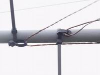
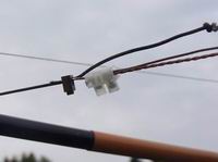
Rather than using larger diameter wire with its associated weight penalty, I decided to add a second wire to the Reflector structure, spaced a small distance from the first, in much the same way as the elements of a Cage Dipole. The simplest way to do this on the classic Hexbeam support structure is to join the two wires at the Centre Post terminal and at the element tips, but to keep them apart at the "knee". The two photos on the right show the arrangement used on my testbed antenna.
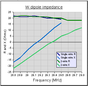 Before assembling a complete beam, I investigated the effect of a second wire on the impedance
of a "W" dipole. The results are shown in the chart on the right and were encouraging. The key
characteristic that determines the bandwidth is how quickly the Reactance changes with
frequency. You can see that the addition of the second wire has had no effect on the Resistance
of the dipole, but it has reduced the rate of change of Reactance quite significantly.
We note that:
- the addition of the second wire has raised the resonant frequency of the dipole by about 200KHz. At first this may seem an odd result because the second wire was longer than the first; but remember that the effect of the 2 wires is to produce a "fatter" conductor which, as we saw in the Wire size & type page, increases the resonant frequency. However, please note that the tuning of the 2-wire Reflector is very sensitive to the geometry at the "knee" and the frequency can decrease, as well as increase, depending on the particular wire positioning;
- for Reactance values between +7 and -7 Ohms the bandwidth has been increased from 300KHz to 450KHz;
- for Reactance values between +12 and -12 Ohms the bandwidth has been increased from 480KHz to 750KHz.
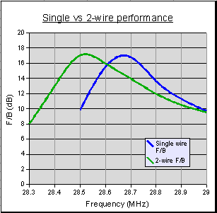 Encouraged by these results I constructed a complete 10m beam with a 2-wire
Reflector. The wires were joined together at the centre post terminal and at the tip of the
Reflector; they were spaced by 2" at the "knee". The chart on the right shows the results compared
to a beam with a single-wire Reflector.
We note that:
- the addition of the second wire has marginally improved the peak F/B performance;
- the tuning has lowered by about 140KHz;
- the F/B>10dB bandwidth has increased from 478KHz to 618KHz (+29%);
- the F/B>12dB bandwidth has increased from 300KHz to 420KHz (+40%);
- the F/B>14dB bandwidth has increased from 210KHz to 280KHz (+33%);
- the bandwidth extension is greater at higher frequencies than at lower frequencies - fortuitously this is the area where the SWR is lowest;
- SWR (not shown) was hardly affected;
- when scaled to 14MHz, these results indicate that a Hexbeam with a 2-wire Reflector would deliver F/B>10dB across all but 50KHz of the 20m amateur band.
In an effort to find more-practical, but still effective, ways of implementing the technique, I built a range of different broadband Reflectors. With a Reflector up at 20ft I measured its resonant frequency, and its +12/-12 Ohm reactance bandwidth - a useful guide to the F/B bandwidth it will deliver. All Reflectors were 2754mm (108.4") long; in the case of the 2-wire designs the shorter of the two wires was 2754mm long
Various 2-wire geometries were tried; in all cases the wires were joined at the centre-post terminal and at the Reflector tip, and separated at the mid-point "knee" by horizontal distance "a" and vertical distance "b".
The results are presented in the table in order of increasing bandwidth:
| Reflector | Resonant frequency | +12/-12 Ohm Bandwidth (KHz) |
| Single wire reference | 28,440 KHz | 460 KHz |
| RG174 coax | -107 KHz | 500 KHz |
| 2-wire a=2.5" b=0.5" | -680 KHz | 571 KHz |
| 300 Ohm slotted ribbon | -265 KHz | 576 KHz |
| 450 Ohm "window" | -440 KHz | 600 KHz |
| 2-wire a=1" b=1" | -110 KHz | 600 KHz |
| 2-wire a=2" b=1" | +193 KHz | 622 KHz |
| 2-wire a=1.5" b=3"" | +626 KHz | 672 KHz |
| 2-wire a=2" b=1.5" | +460 KHz | 711 KHz |
| 2-wire a=0" b=4" | +710 KHz | 720 KHz |
We note that:
- generally, the "fatter" the Reflector, the greater the bandwidth and the higher the resonant frequency;
- in the case of RG174, 300 Ohm ribbon and 450 Ohm window, the lengthening effect of the insulator dielectric has more than compensated for the shortening effect of the "fatter" wire, and the resonant frequency has dropped;
- the 2-wire Reflector with a=2.5" and b=0.5" (typical of the shallow spreader angle we might encounter at the 10m position of a 5 band Hexbeam) has lowered the resonant frequency considerably with only a modest improvement in bandwidth. The small 0.5" vertical spacing at the knee means that there is only significant wire separation on the "outer" half of the Reflector, reducing the net "fattening" effect. At the same time the 2.5" horizontal separation has produced a significant increase in the net Reflector length. The shift in resonant frequency is almost entirely accounted for by Reflector lengthening - indicating that there is minimal "fattening" effect;
- high b/a ratios on a 2-wire Reflector (typical of the steeper spreader angle encountered on the uppermost band of a multiband array) produce the most effective "fattening", driving the resonant frequency up and delivering maximum bandwidth;
- the resonant frequency of a 2-wire Reflector is critically dependent on the wire spacing at the knee. A change from a=2.5"/b=0.5" to a=2"/b=1.5" has shifted the resonant frequency by 1.4MHz!
2. Modified Reflector shape
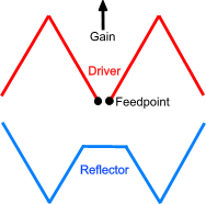 The major contributor to the HexBeam's high Q is its low Radiation Resistance (about 22 Ohms).
This is caused by the current cancellation that occurs where the inner halves of the dipole
elements come together at an acute angle at the Centre Post. If this part of the Hexbeam
geometry can be avoided, the radiation Resistance will increase and the Q will drop.
The drawing on the right shows one way of achieving this. EZNEC work shows that there is little point in making the same change to the Driven element: it has little effect on the F/B bandwidth; it damages the array SWR significantly; and it would probably require some extra mechanical support to be provided at the feed point. In the following discussions this geometry is referred to as the "Hybrid" shape, to distinguish it from the "Classic" shape. Good results were achieved on my 10m test array by placing the "cross connect" at a point on the support spreader 20" out from the Centre Post
The altered geometry means that, for a given Reflector length, the "knees" will be further out from the centre post and thus require slightly longer support spreaders; however this is offset to an extent because the Hybrid shape pushes the array tuning down in frequency and so the Reflector can be shorter for a given frequency. Further shortening can be achieved by using insulated wire. By placing most of the "End Spacing" on the Driver side of the support structure it should be possible to arrive at a "symmetric" design which lies neatly in the horizontal plane.
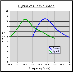 The chart on the right compares the measured performance of a Hybrid shape Hexbeam compared with
the Classic shape. In both cases the Reflector was constructed of #16 bare copper wire; but in
the case of the Hybrid the Reflector had to be shortened by 1" in order to get the tuning
in-band. The "cross-connect" on the Hybrid design was positioned at a point on the support
spreaders 20" out from the Centre Post, and the Driver/Reflector tip spacing was 10.5"
We note that:
- the F/B>10dB bandwidth has increased from 478KHz to 550KHz;
- this bandwidth improvement has been gained entirely on the high frequency side of the peak F/B where the SWR is lowest;
- despite having a 1" shorter Reflector, the Hybrid design still tuned 280KHz lower in frequency;
- although not shown on the chart, the Hybrid shape delivers a small, but useful, improvement in SWR.
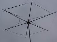
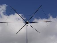 Of course there is no reason why these two bandwidth extension approaches - "fatter" elements
and Hybrid shape - should not be combined. Consequently I constructed a total of 11 arrays using
various "fatter" Reflector wire types in Hybrid and Classic shapes. The photos on the right show
a couple of examples: the first has a Reflector of RG58 coax in the hybrid shape; the second has
a Reflector of 450 Ohm window in the hybrid shape and a Driver of 300 Ohm window in the classic
shape.
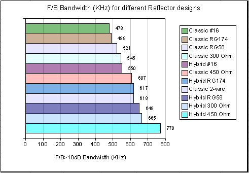 Each array was tested at a
height of 20' for its F/B performance. The bar chart summarises the results in order of increasing
bandwidth.There are no surprises here. The fatter the wire the better the bandwidth, and the Hybrid
shape outperforms the Classic shape for each wire type. Some of the arrangements are more
practical than others: the 2-wire Classic design delivers
good performance, but its tuning is quite unpredictable; the Hybrid shape using 450 Ohm window does
best of all, but construction is more difficult with this type of wire.
An attractive option is the Hybrid shape using RG58 coax: it delivers a 36% increase in bandwidth; it is relatively easy to handle; and the tuning is quite predictable. Scaled to other frequencies, it would cover all of the 15m band and all but 25KHz of the 20m Band.
The effectiveness of the Hybrid shape led me to model an "extreme" version in which the Reflector is kept as far from the Centre Post as possible. A quick calculation showed that this would increase the turning radius by only 15%, and EZNEC modelling predicted that it would outperform any of the options considered so far, even when implemented with relatively thin #16 gauge wire. Practical tests on a 10m test antenna confirmed the modelling results and led to the design and evaluation of a complete 5 band prototype; you can read about it on the Broadband Hexbeam page.
Please note that none of the earlier techniques have been evaluated on a multiband design, nor have their dimensions been optimised. I would recommend that you only try them if you have facilities to evaluate an antenna's performance accurately and are prepared to experiment! If not, stick to the well-proven Broadband or Classic designs.