Hexbeam multiband performance

A very attractive feature of the normal construction approach used for the Hexbeam is that the wire elements for several different bands can be nested to form a multiband antenna. We will look at how this "multibanding" affects the performance of the beam.
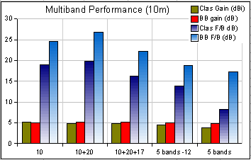
Shown below are performance data charts for a 5 band (20m thru 10m) multiband Broadband Hexbeam and a Classic Hexbeam. On each chart the extreme left hand data is the monoband performance; the data to the right then shows progressively how the performance changes as further band elements are added to the structure.
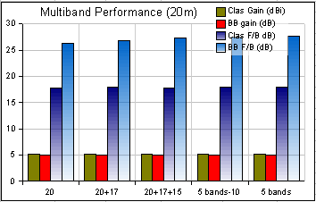
These data lead to the following conclusions:
- monoband performances are all very similar, as would be expected;
- the 20m performance is relatively immune to the addition of other bands;
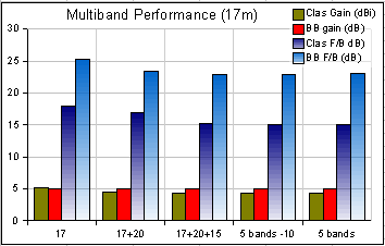
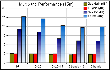
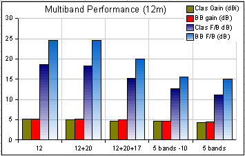
- the 17m, 15m, 12m and 10m band performance, particularly the F/B ratio, suffers to varying degrees from the addition of other bands. The general trend is that the bands closest (in distance and in frequency) have the greatest effect;
- the Broadband Hexbeam Gain is generally affected less than the Classic Hexbeam Gain;
- the biggest performance degradation occurs at 10m when 12m elements are added to the structure.
It is not surprising that there is significant interaction between the 10m and 12m band elements. The "dished" structure typical of most Hexbeams means that the wires for these bands may only be separated by a couple of inches. Modelling shows that if you cannot achieve the 4" separation between the 10m and 12m wires assumed in these data, the performance will degrade dramatically. The modelling also shows that it is separation at the centre post (where element currents are highest) that matters most; so simply dropping the 10m feedpoint is an easy solution, even though it may result in "sloping" wires. We also saw on the Broadband Hexbeam - In depth page that moderately larger End Spacing does not compromise the performance of the new design, so increasing the End Spacing on a Broadband Hexbeam to allow the 12m wires to be mounted higher in the support structure could be an option.
Interestingly, simulations also suggests that if you could achieve band spacing throughout the structure that was proportional to wavelength (in a manner similar to a cubical quad), full monoband performance could be achieved for every band. The spacings would need to be:
- 20m - 17m : 15"
- 17m - 15m : 12"
- 15m - 12m : 10"
- 12m - 10m : 9"