Broadband Hexbeam - Photographs
This page contains photographs of the testbed antenna which I used to develop the new 5-band Broadband Hexbeam. You can "click" on any of the photos to see a higher-resolution version. Please note that the construction techniques are not necessarily designed to be long-lasting - rather, they were chosen to facilitate changes to wire dimensions and geometry.
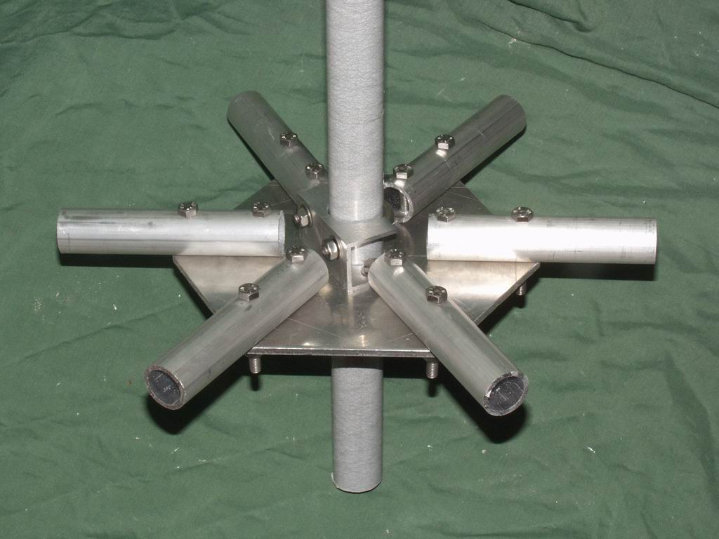 This is the all-important hub. The 1/4" thick aluminium baseplate attaches to a fibreglass
Centre Post using 2 short sections of aluminium channel and U-bolts, one above and one below the plate.
The spreaders slot into the aluminium tubing which is bolted to the baseplate; this method
allowed the spreaders to be replaced easily when I was investigating how best to achieve the
increased size needed for the new design. You can find detailed dimensional information in
the following PDF files:
This is the all-important hub. The 1/4" thick aluminium baseplate attaches to a fibreglass
Centre Post using 2 short sections of aluminium channel and U-bolts, one above and one below the plate.
The spreaders slot into the aluminium tubing which is bolted to the baseplate; this method
allowed the spreaders to be replaced easily when I was investigating how best to achieve the
increased size needed for the new design. You can find detailed dimensional information in
the following PDF files:
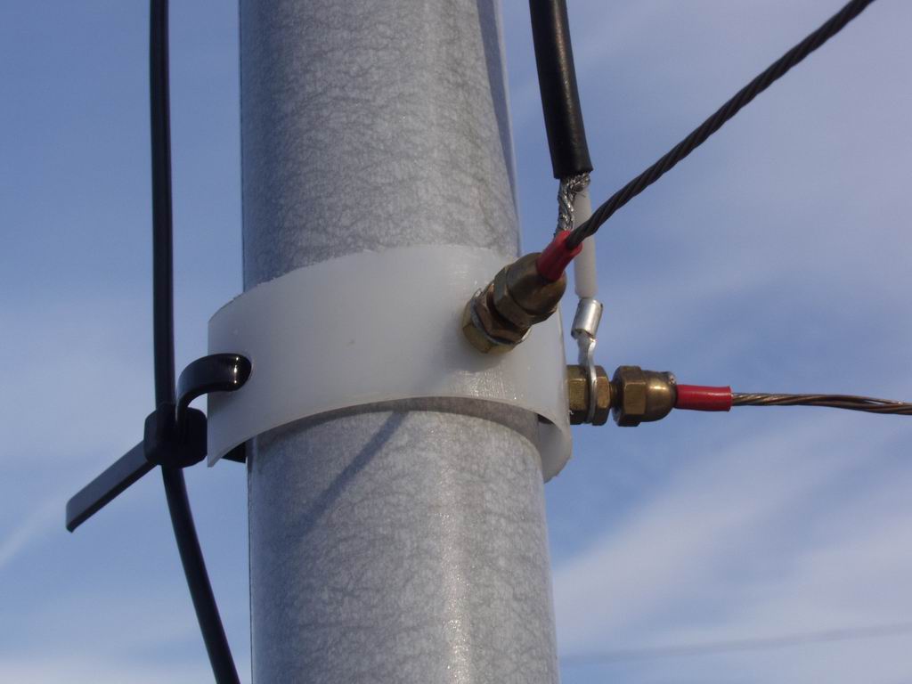 This is the arrangement I used for the Centre Post connections. Brass "dome nuts" soldered to
the end of the wire elements are screwed onto 4mm brass bolts. The bolts pass through a piece of
"curved plastic" cut from a used sealant container. The plastic is secured to the Centre Post
by a tie-wrap; this arrangement allowed me to slide the connections up and down the Post to
accomodate different wire element lengths.
This is the arrangement I used for the Centre Post connections. Brass "dome nuts" soldered to
the end of the wire elements are screwed onto 4mm brass bolts. The bolts pass through a piece of
"curved plastic" cut from a used sealant container. The plastic is secured to the Centre Post
by a tie-wrap; this arrangement allowed me to slide the connections up and down the Post to
accomodate different wire element lengths.
Of course there are no Reflector connections needed at the Centre Post with the new design!
 The spreaders used were cheap fibreglass "crappie poles" left over from an earlier project. The
increased spreader length required for the broadband design was achieved by combining 5 sections
from two 4m poles; here, you can find
details on how I assembled the spreaders and the
arrangement I used at the spreader tips. My final spreader lengths
were 135", held out 4" from the Centre Post by the Baseplate tubing, and this provided the 130"
horizontal radius required for the top 20m elements. Using other materials for the spreaders
will likely require slightly different lengths because the "bow" will be different.
The spreaders used were cheap fibreglass "crappie poles" left over from an earlier project. The
increased spreader length required for the broadband design was achieved by combining 5 sections
from two 4m poles; here, you can find
details on how I assembled the spreaders and the
arrangement I used at the spreader tips. My final spreader lengths
were 135", held out 4" from the Centre Post by the Baseplate tubing, and this provided the 130"
horizontal radius required for the top 20m elements. Using other materials for the spreaders
will likely require slightly different lengths because the "bow" will be different.
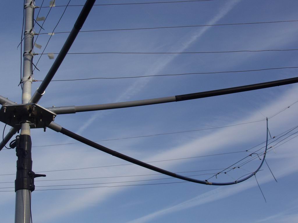
Notice the paper tabs stuck to the Driver wires near the Centre Post? They were marked up with the present wire dimensions - it was so easy to lose track of the lengths once I started trimming!
 These are the temporary fixings used to attach the wire elements to the spreaders. The use of tie
wraps enables the attachment points to be slid along the spreaders easily. The extension cords
on the 17m, 15m and 12m wires in the photo provide fixings when the height of these elements in the
support structure was such that they did not reach to the spreaders.
These are the temporary fixings used to attach the wire elements to the spreaders. The use of tie
wraps enables the attachment points to be slid along the spreaders easily. The extension cords
on the 17m, 15m and 12m wires in the photo provide fixings when the height of these elements in the
support structure was such that they did not reach to the spreaders.
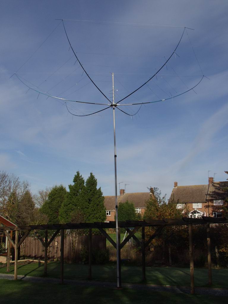
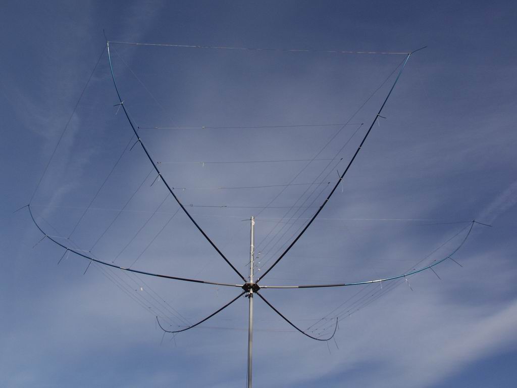 Here you can see the fibreglass telescopic mast and the final array at the test height of 20ft.
The revised shape of the Reflectors and the extensions to the spreaders can be clearly seen.
Here you can see the fibreglass telescopic mast and the final array at the test height of 20ft.
The revised shape of the Reflectors and the extensions to the spreaders can be clearly seen.
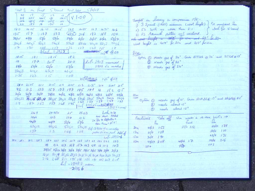 And finally, this is what it was all about ....... a sample of the 1000+ measurements in my lab notebook which
involved me walking 50Km between the two ends of the test range!
And finally, this is what it was all about ....... a sample of the 1000+ measurements in my lab notebook which
involved me walking 50Km between the two ends of the test range!