Hexbeam modelling (Part 1)

I have heard some Hexbeam enthusiasts claim that the antenna cannot be modelled succesfully by packages such as EZNEC. This has not been my experience.
It is true that the unique shape of the Hexbeam calls for some care in choosing the number of segments to be used in the model - particularly around the feedpoint where the two halves of the Driver form an acute angle. My experience is that you need quite small segment lengths in this area. But you cannot simply use short segments here, and longer segments elsewhere - abrupt changes in segment length need to be avoided.
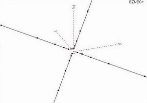
One solution is to use short segments throughout the model. However this results in a large number of segments, longer computation times, and on a 5 band Hexbeam model you will likely exceed the 500 segment limit of some of the "entry level" simulation packages. A better solution is to used "tapered segmentation"; with this approach, segments are made short in the critical area but are gradually lengthened as you move away from it. The diagram on the right is an expanded view of a Hexbeam model with tapered segmentation to show you the general idea:
Two necessary conditions for demonstrating that a model is reliable are that it "converges", and that it exhibits a low "Average Gain (AG)" figure. Convergence simply means that a further increase in the number of segments produces only an immaterial change in the results output from the model. L.B.Cebik, W4RNL, described this in more detail.
The Average Gain of a model is the ratio of the total power radiated by the antenna - integrated over all 3 dimensions - to the power applied to it; clearly, in a loss-free environment these two figures should be the same. L.B.Cebik quotes the following rules:
- AG>0.8dB "Model is subject to question and should be refined"
- AG>0.4dB "Model may be useful, but adequacy can be improved"
- AG>0.2dB "Model is quite usable for most purposes"
- AG<0.2dB "Model is considered to have passed the test and is likely to be highly accurate"
| Segmentation method | Number of segments | Average Gain | Input Impedance | Forward Gain | F/B |
| EZNEC (Minimum recommended) |
18 | +2.19dB | 14.9 + j 8.4 | 7.9dBi | 15.4dB |
| EZNEC (Conservative) |
26 | +1.87dB | 16.4 + j 9.1 | 7.5dBi | 15.5dB |
| Tapered | 80 | -0.03dB | 23.5 + j 12.3 | 5.8dBi | 16.0dB |
| Linear | 300 | 0.00dB | 24.3 + j 13.5 | 5.7dBi | 16.2dB |
It is interesting to note the effects that different segmentation schemes have on the results produced by an EZNEC Classic Hexbeam model. The table shows the Average Gain, Input Impedance, forward Gain and F/B ratios of the same 20m HexBeam model for four different levels of segmentation.
As you can see, both of the EZNEC "automatic" segmentations produce quite erroneous figures. Although it can be argued that subtracting the Average Gain figure from the Forward Gain value corrects this particular parameter, we are still left with some very misleading Input Impedance values. On the other hand tapered segmentation produces values which for all practical purposes are the same as those from the 300 segment model, with the advantage that a 5 band HexBeam can be modelled with as little as 400 segments.
Translating the dimensions of a Hexbeam (which are usually quoted in terms of the "Half Driver length", the "Half Reflector length" and the "End Spacings") into the XYZ coordinates for an EZNEC model is itself a challenge; add to that a requirement to taper the segmentation and it becomes a major exercise. Fortunately, Leo (K4KIO) has done all the hard work for us and provided a spreadsheet which takes Hexbeam dimensions as inputs and which produces an output file that can be read directly into EZNEC.
In Part 2 of Hexbeam modelling we'll take a look at how EZNEC predictions compare to "real world" measurements.