Hexbeam multiband matching
Introduction
A straightforward approach to feeding a multiband Hexbeam is to connect a separate feeder to each band's Driver and use a remotely controlled switchbox mounted below the antenna to switch the main feedline to the required band. With this method you can expect to achieve SWRs similar to those of a monobander; if you wish to improve things on the Classic Hexbeam you can use either of the monoband matching techniques described earlier. The only potential problem is that the unused feeders, if not terminated with a 50 Ohm load, and depending on their length, may tune the unused Drivers to resonance and cause some interaction with the "in use" elements.
However, most Hexbeam builders will prefer the convenience of using a single feedline for all bands. This section describes some of the potential pitfalls of this approach. It is an area of Hexbeam performance which is often misunderstood and which, if the wrong choices are made, can lead to disappointing results. Hopefully, after reading this section you will understand the principles behind multiband matching and be able to make informed choices when building your antenna.
Summary
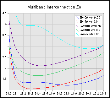
The key choices to be made are: at which band position to feed the antenna, and what type of interconnecting cable to use between the various band elements. Later in this section there is a detailed discussion which concludes that "top feeding" (i.e. feeding at the 20m position on a 20m-10m array) and using 50 Ohm coaxial cable for the band interconnections is preferable. By way of summary we present here a chart showing the effect on the 10m SWR of a top-fed 5-band Broadband Hexbeam when we change the characteristic impedance of the interconnecting cable.
The SWR curves for five different cable types are shown:
- Zo=50 / Vf=0.66 representing commonly available coaxial cable such as RG213 or RG58;
- Zo=70 / Vf=0.9 typical of twin-feeder that could be constructed with very careful attention to insulation thickness and line spacing. See the Twin feed experiment page for more details;
- Zo=100 / Vf=0.66 representing twin-feeder constructed from two lengths of coax, series connected;
- Z0=100 / Vf=0.9 typical of twin feeder constructed without careful wire selection. See the Twin feed experiment page for more details;
- Zo=25 / Vf=0.66 representing twin-feeder constructed from two lengths of coax, parallel connected.
From the chart we conclude that:
- Twin feeder constructed from parallel-connected coax (cyan curve) or series-connected coax (mauve curve) produces an unacceptable SWR;
- Twin feeder constructed from carefully selected cable (red curve) produces the lowest SWR, but its SWR bandwidth is worse than 50 Ohm coax (blue curve);
- Twin feeder constructed without careful attention to cable type (green curve) produces poor minimum SWR and narrow SWR bandwidth;
- The SWR curve deteriorates rapidly moving from 70 Ohm twin feeder to 100 Ohm twin feeder - the range in which the Zo of most home-constructed lines lie;
- 50 Ohm coax produces good SWR figures and the best SWR<2 bandwidth.
Overall there seems little point in using anything other than readily available 50 Ohm coaxial cable. RG58 should be good for power levels up to about 400 Watts, above which RG213 or an equivalent should be used.
Multiband matching - in depth
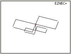
We will now look in detail at the mechanisms that produce these results. To keep things simple we'll examine the 2 band (20m/10m) array shown to the right, rather than a 5 band array. Although the Classic geometry is shown, the arguments apply equally to the Broadband design. We'll look at 4 feed options:
- Top fed / 50 Ohm interconnecting cable;
- Top fed / 300 Ohm interconnecting cable;
- Bottom fed / 50 Ohm interconnecting cable;
- Bottom fed / 300 Ohm interconnecting cable.
I chose 50 Ohm and 300 Ohm as typical of the "low Zo" and "high Zo" impedances that might be used for the interconnections. These 4 feed combinations encompass the majority of situations that are likely to be encountered in practice and give a good insight into the behaviour of the antenna. Intermediate cable impedances, or feedpoints in the middle of the array, produce results that fall between these "extremes". Interconnections with Zo higher than 300 Ohms will cause serious matching problems for reasons that will become evident later - they should be avoided.
We will see that there are 2 main mechanisms causing impedance transformations within the feed structure:
- any interconnecting cable that is between the array feedpoint and the band in use will potentially cause an impedance transformation. The higher the characteristic impedance of the cable, the longer it is, and the lower its velocity factor, the greater the transformation;
- any interconnecting cable attached to the Driver of the band in use, but on the opposite side to the array feedpoint, will act like an open-circuit stub shunting the Driver with a capacitive reactance.
We will now look at how the various feed options affect the SWR, firstly on 20m and secondly on 10m.
20 metres
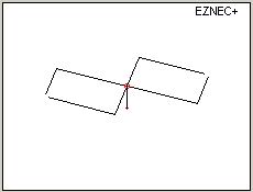
To keep things simple we'll assume that the Driver of the band not being used presents a very high impedance to the interconnecting cable and can therefore be ignored. The 20m picture then reduces to a 20m HexBeam attached to a length of interconnecting cable as shown. The physical length of the interconnecting cable is assumed to be 30" - typical of the 20m / 10m separation seen on many support structures.
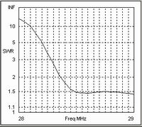
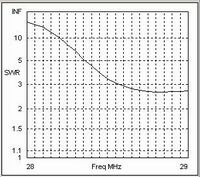
a) Top Feed / 50 Ohm interconnections
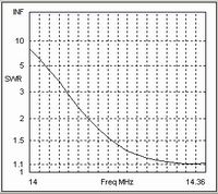
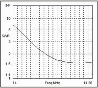
For reference, the first chart shows the SWR curve that would result from using a dedicated feedline i.e. no interconnections. The second chart shows what happens when we feed our array at the top - the 20m position - and use 50 Ohm cable with a velocity factor of 0.66 for the band interconnections. We note that there has been a marked improvement in SWR at all but the lowest frequencies, where it is slightly higher.
At first sight this might seem a surprising consequence of simply hanging 30" of cable across the feedpoint. The explanation is that the impedance of the Driver at the design frequency is inductive [25 + j14], and the effect of the interconnecting cable is to place shunt capacitance equivalent to about 75pF across it; the result is a "capacitive Beta match" which increases the resistive component and reduces the reactance, typically to [29 +j10], thereby improving the SWR from 2.2 to 1.8. This "matching mechanism" works even better at the higher end of the band where the Driver feedpoint is more inductive; however it works against us at the bottom of the band where the Driver is capacitive and we are compounding the problem by adding more capacitive reactance. This mechanism is the major factor why the SWR of a multiband Classic Hexbeam can be better than a monobander.
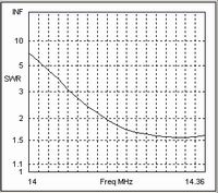
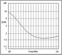
b) Top Feed / 300 Ohm interconnections

If we now change the interconnecting cable to one with a higher characteristic impedance of 300 Ohms we get the SWR curve shown in the third chart. Again there has been a marginal improvement in the SWR at the higher end of the band. However, a combination of the increased characteristic impedance and the higher velocity factor of the cable (assumed to be 0.88) reduces the benefit considerably - equivalent to a capacitor of about 5pF.
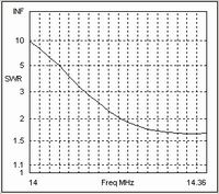
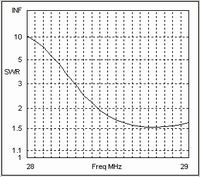
c) Bottom Feed / 50 Ohm interconnections
We will now move the feedpoint to the bottom of the array and revert to 50 Ohm cable for the band interconnections. We get the SWR curve on the right which is indistinguishable from the reference curve shown in the first chart. This is not surprising because we are simply connecting to the 20m Driver through an extra 30" length of 50 Ohm cable, which will have no effect on the SWR.
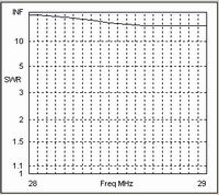
d) Bottom Feed / 300 Ohm interconnections
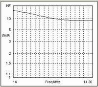
However, a very different picture emerges when we bottom feed and use 300 Ohm cable for the band interconnections. The introduction of 30" of high Zo transmission line between the feedpoint and the 20m Driver has transformed its impedance from [25 +j14] to [27 +j93], taking the SWR from 2.2 to around 10. We have an unacceptable SWR across the whole band.
e) Bottom Feed / 300 Ohm interconnections / Short Driver
All is not lost however! Note that the high Zo interconnection has introduce a large inductive reactance but has hardly changed the resistive component. We have seen in the earlier "Matching" section that, within limits, we can make the Driver capacitive by shortening it without detriment to beam performance. If we make the Driver 9% shorter than the Reflector we can almost totally compensate for the inductance introduced by the 300 Ohm interconnection. We then get the SWR performance shown in the sixth chart which is quite acceptable.
10 metres
As in the 20m case we'll assume that the Driver of the band not being used presents a very high impedance to the interconnecting cable and can therefore be ignored. The 10m picture then reduces to a 10m HexBeam attached to a length of interconnecting cable as shown.
f) Bottom Feed / 50 Ohm interconnections
For reference, the first chart shows the SWR curve that would result from using a dedicated feedline i.e. no interconnections. The second chart shows what happens when we feed our array at the bottom - the 10m position - and use 50 Ohm cable with a velocity factor of 0.66 for the band interconnections. As in the 20m Top Fed case, we notice a general improvement in SWR brought about by the shunt capacitive effect of the interconnecting cable, particularly at the top of the band. Interestingly there is some evidence on this chart of a second SWR minimum beginning to appear.
g) Bottom Feed / 300 Ohm interconnections

If we now change the interconnecting cable to one with a higher characteristic impedance of 300 Ohms we get the SWR curve shown in the third chart. Again there has been a noticeable improvement in the SWR at the higher end of the band. The lower value of shunt capacitance, resulting from the increased characteristic impedance and the higher velocity factor, provides a slightly better overall match than the 50 Ohm case.
h) Top Feed / 50 Ohm interconnections
We will now move the feedpoint to the top of the array and revert to 50 Ohm cable for the band interconnections. Again we get an SWR curve which is indistinguishable from the reference curve because we are simply connecting to the 10m Driver through an extra 30" length of 50 Ohm cable, which will have no effect on the SWR.
i) Top Feed / 300 Ohm interconnections
Once again the introduction of 30" of high Zo transmission line between the feedpoint and the Driver has transformed its impedance radically, but the increased electrical length of the line at 28 MHz has made the effect much more severe than it was at 14 MHz.
In fact we now have to shorten the Driver to 26% less than the Reflector to achieve moderate SWRs - even then they do not fall below 2.6. Worse yet, the very short Driver has begun to compromise the Gain and F/B performance of the beam.

From these analyses we note that:
- the shunt effect of the interconnecting cable can improve the SWR performance of a multiband Classic Hexbeam over a monobander;
- if 50 Ohm line is used for the interconnections, "regular" Reflector / Driver resonance ratios between 1.015 to 1.02 will give satisfactory performance;
- if higher impedance line is used for the interconnections, the Drivers of the bands furthest from the feedpoint will need to be shortened to keep the SWR down to an acceptable level. Depending on the line used, there may come a point where the Driver cannot be shortened enough before beam performance suffers;
- the interdependence between Driver length and Zo of the interconnecting cables means that you cannot "mix and match" design dimensions and expect to get satisfactory performance. In other words don't expect the dimensions published for high impedance interconnecting cable to work with 50 Ohm cable, and vice-versa;
- this interdependence also means that you need to make sure the impedance of your interconnections matches that of the design you are following. Using "any old cable" will likely produce disappointing SWR figures! See my page on twin feed experiments for more information.
The real-world situation is somewhat more complex than this analysis would indicate. For one thing the unused bands do not present an infinite impedance to the interconnecting cable - the impedances tend to be high but have a negative resistive component, indicating that these elements are picking up radiation and returning energy to the feed system. Nevertheless the principles established above broadly apply.
To round off this section we will look at two charts that summarise the SWR performance with the 4 feed options:
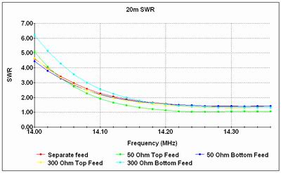
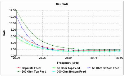
We conclude that:
- with the exception of a Top Fed array having a high Zo line, any of the options can produce a reasonable SWR provided that suitable Driver lengths are chosen;
- top Feeding with 50 Ohm interconnections results in the best SWR compromise and has the added advantage that it does not require extreme Reflector / Driver ratios.