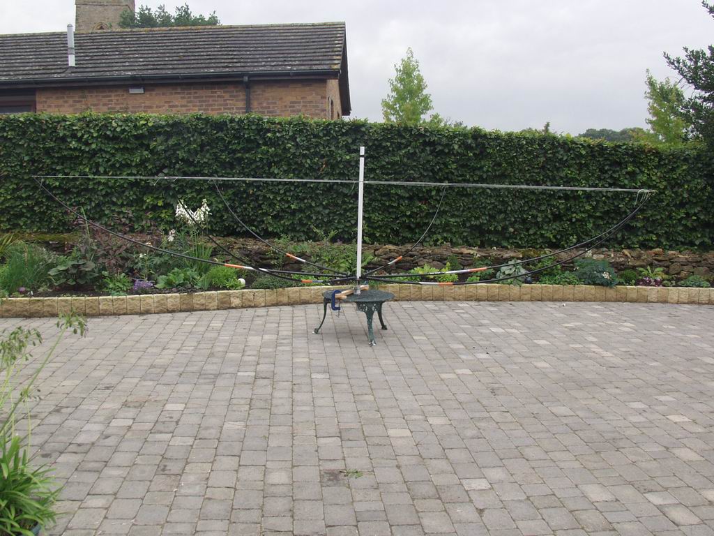
Classic Hexbeam - Photographs
The photographs on this page show some of the construction techniques I used in building two 4-band Classic Hexbeams. The photographs may give you some ideas on how to build one for yourself, but if you need step-by-step instructions take a look at K4KIO's website. My Mk1 beam suffered in the gales which hit the UK in early 2007, so I built a Mk2 using a more robust baseplate and centre post arrangement. Click on any of the photos to see a "supersize" version.
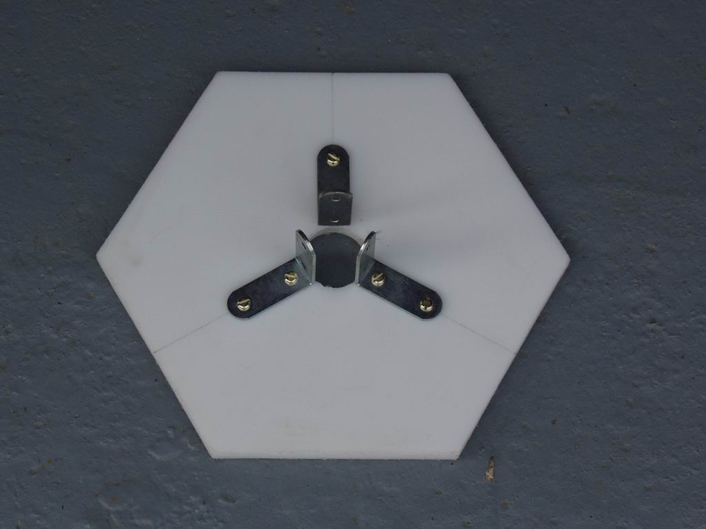
These two photographs show the original baseplate and centre post arrangement. The baseplate was made from a plastic kitchen chopping board and the centre post was cut from a length of PVC pipe. They were fixed together with 3 angle brackets; it was this mounting arrangement which failed in the strong winds. I've no doubt that the choice of materials would have been fine if had I joined them more securely.

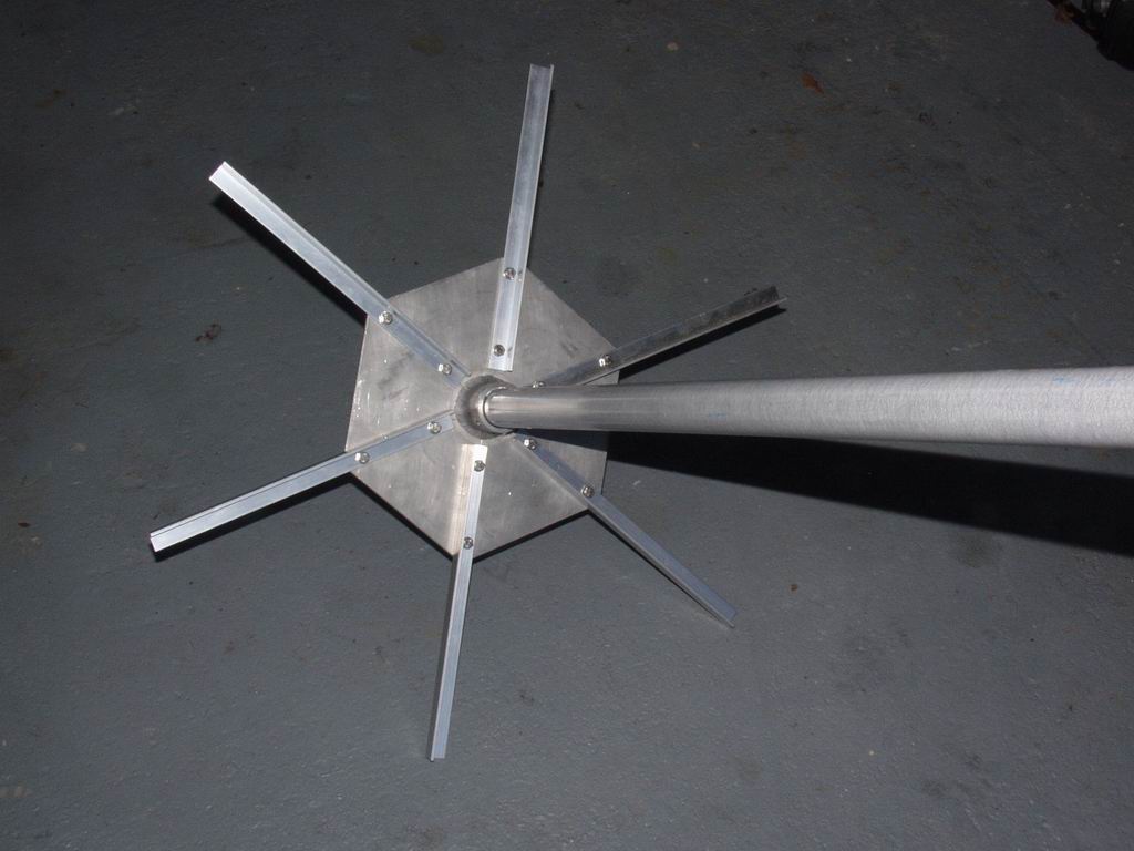
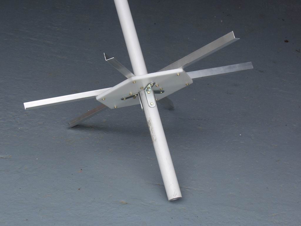
I was determined that the Mk2 would not suffer the same fate, so I had a local engineering firm make me up a 1/4" aluminium baseplate welded to a thick-wall aluminium pipe. I used a fibreglass centre post instead of the original PVC one, and thicker aluminium angle to support the spreaders. The angle was fixed to the baseplate with stainless nuts and bolts.
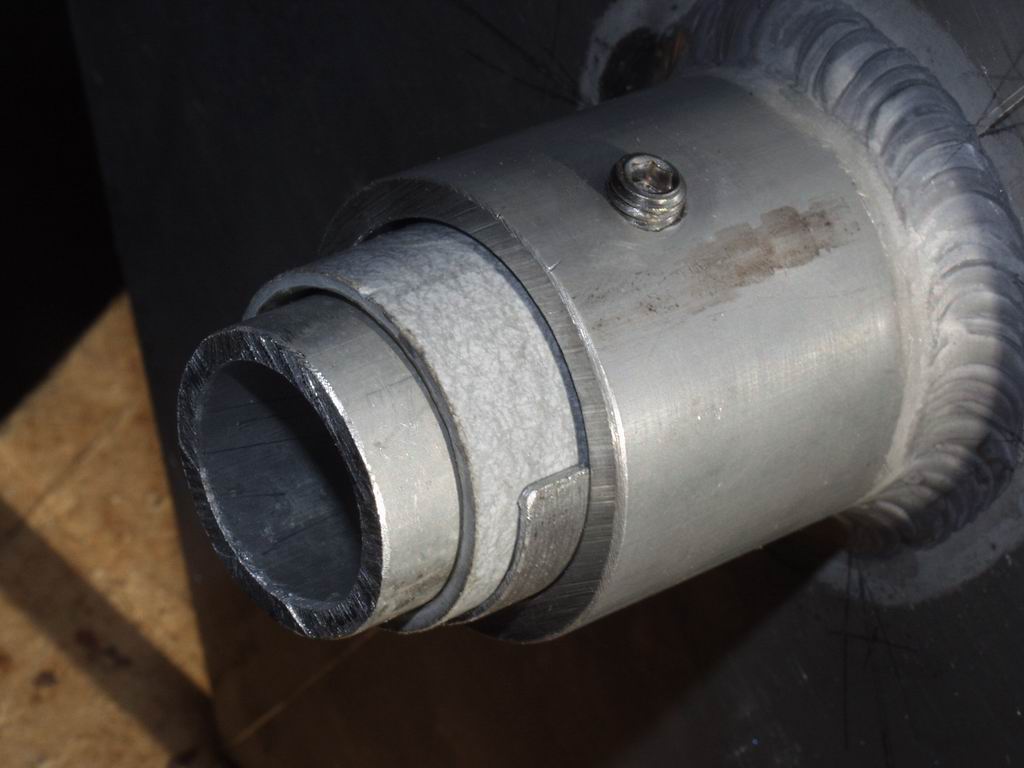
The picture on the right shows the cross-section detail of how I fixed the centre post inside the baseplate tube. A 1/3" hexagon head grub screw passes through a threaded hole in the tube, through a clearance hole in the fibreglass centre post, and presses onto an aluminium insert inside the post. There is also a thin shim to make up the difference between the ID of the baseplate tube and the OD of the centre post. This arrangement feels so strong I believe you could extend the centre post and mount a small VHF/UHF antenna on it.
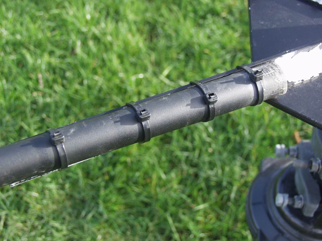
The spreaders are low-cost, 15ft fibreglass fishing poles with the final section unused - it's too "whippy". I fix the poles to the aluminium angle with 4 tie-wraps. Amazingly the poles and their fixings survived when the Mk1 fell to ground from a height of 20ft!
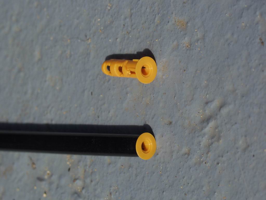
I glued a plastic plug into the end of the spreaders to create a fixing point for the support cords. I used stainless self-tappers that were thin enough not to expand the plug and split the end of the spreader
I strongly recommend that you adopt K4KIO's idea of pulling the structure into shape by cutting 12 equal length nylon cords and stringing them between centre post and spreaders - that way it will automatically take up the perfect hexagon shape. Here's a picture of mine at that stage, before loading the wires.
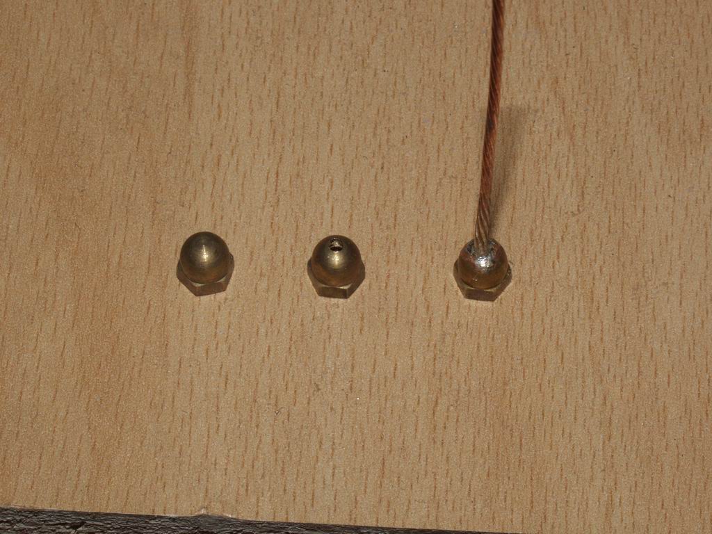
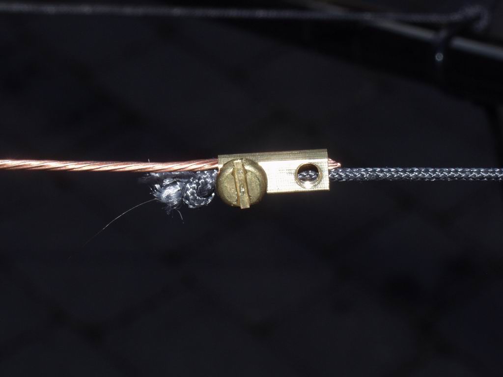
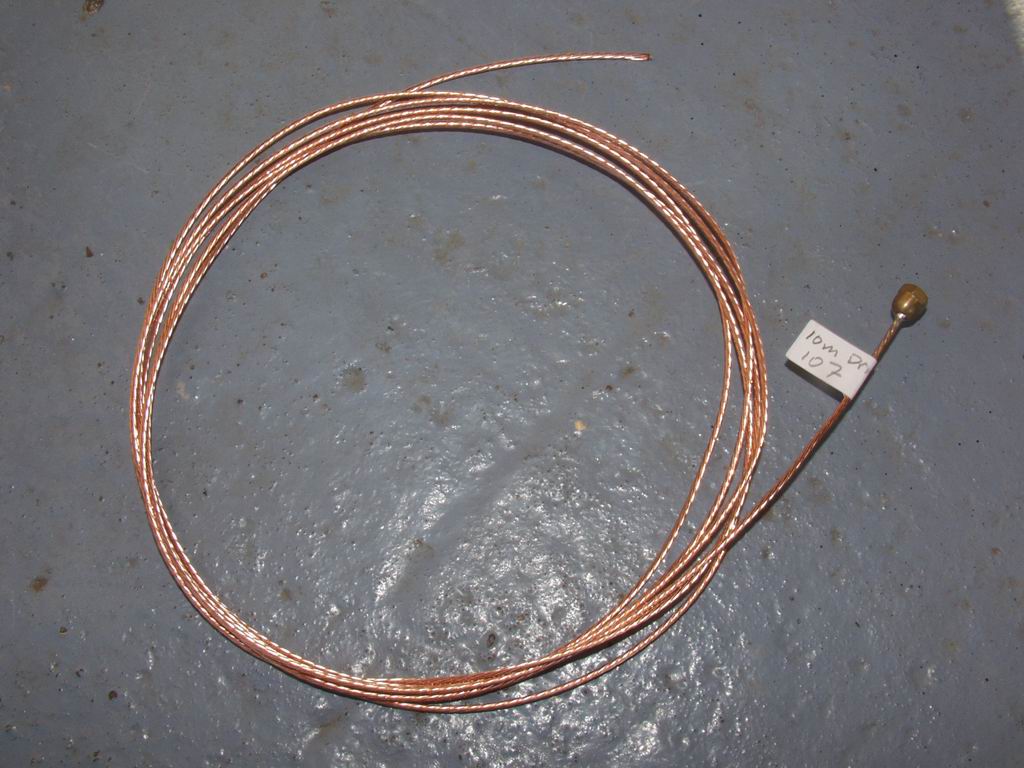
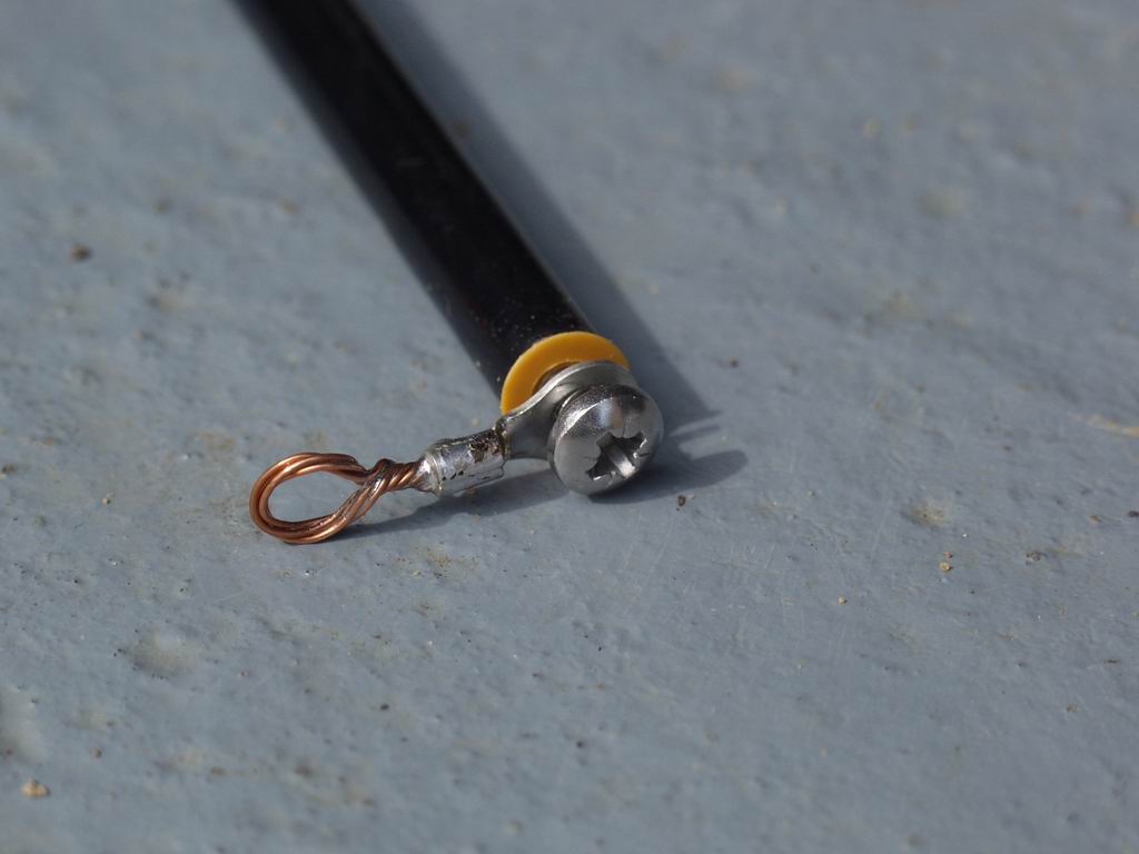
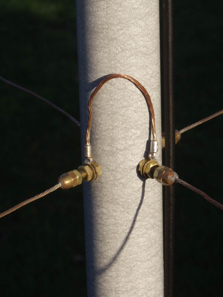
I used 16 gauge 7-strand copper wire - its tough enough to withstand the tension of the spreaders, but not so heavy that the wires sag. To provide a fixing at the centre post I drilled a hole in a 1/6" brass "dome nut" and soldered it onto the wire. At the outer end I fixed the wire to the insulating cords using brass terminal blocks and brass screws; I used 2 screws in the terminal blocks for the top wires because they need to withstand the tension of the spreaders. The right hand picture shows one of the wires cut to length and ready for loading on the support structure; you'll need 4 of these for each band. Be sure to label them with the band, and whether they are Driver or Reflector - it's very easy to get them muddled up!
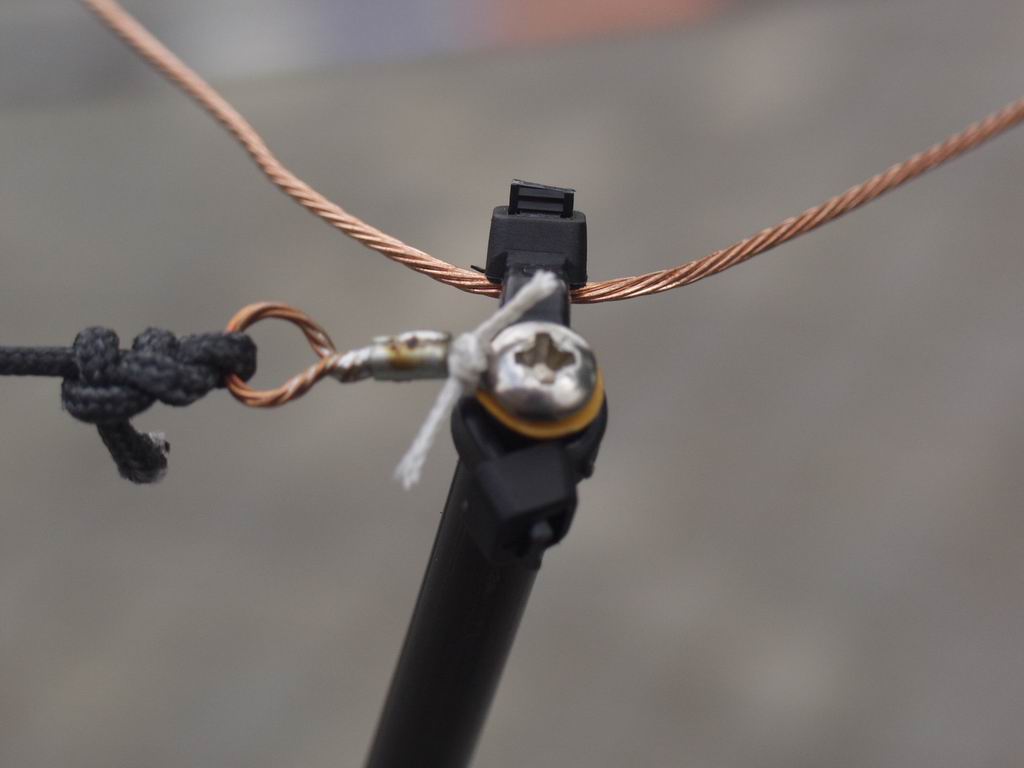
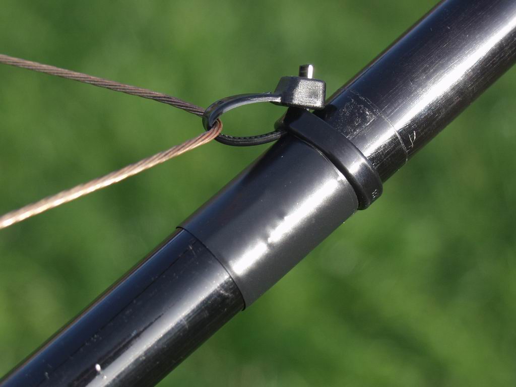

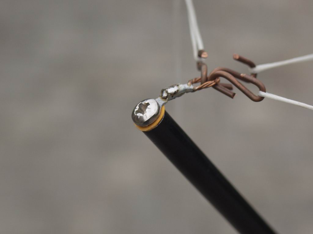
These photos show how the wires are held onto the support structure; I typically use 2 tie wraps - one to form a loop, and the other to tie the loop onto the spreader. I put a couple of turns of insulating tape around the spreader to prevent the loop slipping inwards. The end insulating cord is held by passing a tie wrap through a centre knot. The wires terminate at the centre post on a 1/6" brass screw which has 2 extra nuts on it - one is a locknut for the dome nut and the other holds the spade terminals in place. The right hand photo shows a link joining two halves of a Reflector.
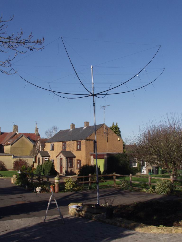
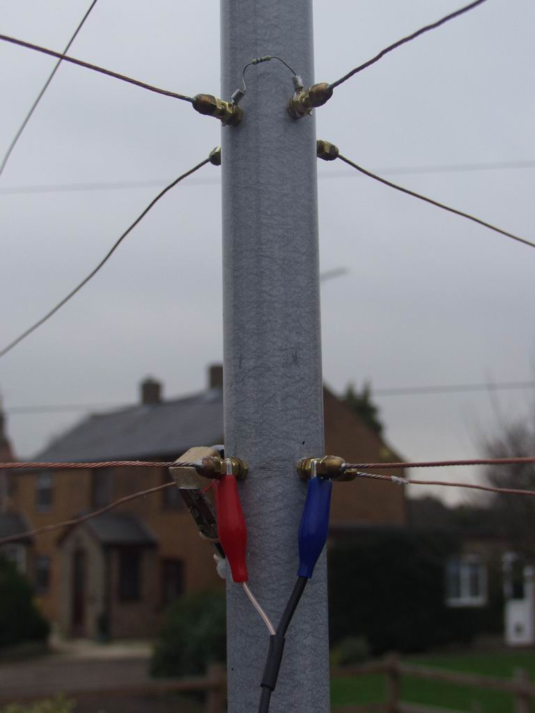
Here's the array in the air on a temporary mast ready for tuning. The excess "tail" on the tie wraps has not yet been cut off in case final adjustments are needed. The middle photo shows a Driver being energized via crocodile clips, while the current in the Reflector is being monitored with a clip-on probe which you can just see behind the red clip. You can also see that the unused Driver is terminated with a 47 Ohm resistor. The right hand photo shows the advantage of terminating the two halves of the Reflector separately - if you trim the wires too short you can recover the situation with a slightly longer link.

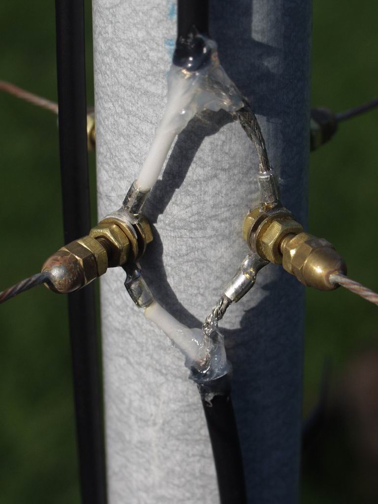

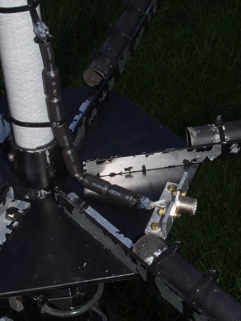
Now we're ready to interconnect the Drivers with 50 Ohm coax, and connect the feedline to the top Driver. I mounted a SO239 socket on the baseplate so that the antenna could be made an independent entity. I also put a ferrite choke balun close to the socket. Be sure to use plenty of water-proofing compound around the exposed ends of the coax. Annoyingly, the black paint is flaking off the aluminium angle although it's OK on the baseplate :(
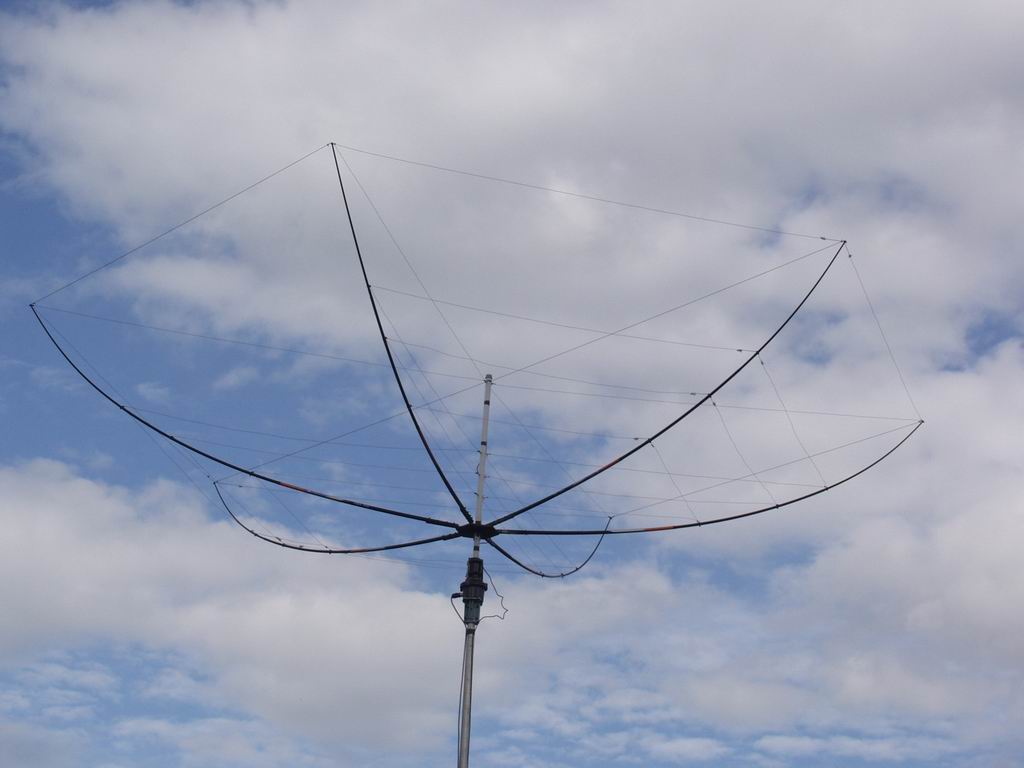
Finally raise to its final height and work the DX!