Hexbeam element shapes
In the quest for physically-small antennas, designers have tried many ways to shorten elements without sacrificing too much performance - bending the dipole element is just one approach amongst many. There are two shapes of "bent element" which interest us in the context of the Hexbeam - their common feature is that they can be easily mounted on a support structure comprising 6 equi-spaced radial spreaders.
1. The M-shaped element
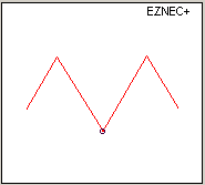
We use the M-shaped element shown in red on the right for the Classic Hexbeam Reflector and Driver, and for the Broadband Hexbeam Driver.
If we remember our High School maths we will be able to work out that, by making the included angles of the M-shaped element 60°, the length of the antenna is halved compared to a linear element. However, it's an unfortunate fact of life that there is a price to pay for making antennas smaller: the M-shape produces 0.4dB less gain than a linear half-wave dipole, and at resonance its impedance is a rather low 23 Ohms. The low impedance matters because it increases the "Q" of the antenna and hence narrows its performance bandwidth.
We may wonder why the M-shape should have such a low resonant impedance. Here's a simplified explanation:
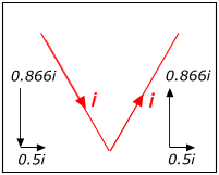
Far right is a magnified drawing of the centre of the M-shape; a current "i" is flowing. This current can be resolved into orthogonal X and Y components with magnitudes i*cos(60) and i*sin(60)as shown. Notice that the Y components are in vector opposition to one another and so cancel one another out. Only the X component - equivalent to half the current in the radiator - contributes to the radiation. Put very simply, although a current of "i" is flowing in the M-shaped dipole it is equivalent to a linear dipole with only "i/2" flowing at its centre.
We would therefore predict that an M-shaped dipole would have a Radiation Resistance one quarter that of a linear half-wave dipole, or 18 Ohms. In practice, complete cancellation of the Y components only occurs at the centre of the element where the opposing currents are very close to one another; so the radiation Resistance is actually a bit higher than the predicted 18 Ohms - in fact it is about 23 Ohms.
2. The U-shaped element
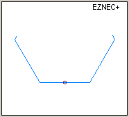
We use the U-shaped element shown in blue on the right for the Broadband Hexbeam Reflector. It has a more "open" geometry than the M-shape; consequently it has a higher resonant impedance of 44 Ohms, a lower Q, and increased bandwidth. It is the increased bandwidth that makes it an attractive choice for the Broadband Hexbeam Reflector.
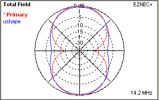
Interestingly, the U-shaped element exhibits about 0.3dBi less gain than M-shape. A look at the azimuth plots of the two shapes, shown far right, explains why. The "bent ends" of the U-shape have resulted in the deep, end-on nulls typical of a linear dipole (and also characteristic of the M-shape) being "filled in". In other words, energy from the U-shape is radiated more evenly in azimuth, and there must therefore be slightly less energy radiated in the broadside direction. Fortunately this does not have a major impact on the Gain of a 2 element beam which uses this shape for its Reflector.
3. Relative performance
It is interesting to compare the performance parameters of our two Hexbeam shapes with those of other physically-short dipoles. The following scatter diagrams show the Gain, resonant feedpoint Resistance and 2:1 SWR bandwidth plotted against turn radius for ten other 20m dipoles that I've modelled, including an end-capacity-loaded dipole, a VK2ABQ Driver, and a "bow-tie" dipole. The M-shape and U-shape performance is shown by the red and blue dots respectively The performance of the two Hexbeam shapes is pretty much consistent with their size - no better and no worse than you might expect from dipoles with turning radii of 9.3 ft and 10.7ft !
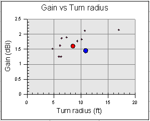
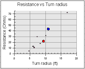
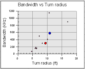
The clear message from these results is that you don't get "something for nothing" - generally, the bigger the turning radius the higher the Gain, Impedance and SWR bandwidth. It should therefore come as no surprise that a Hexbeam formed from M-shaped or U-shaped elements has less gain, and a narrower bandwidth, than a full-size 2 element Yagi.
4. Resonant length
The "bending" of a piece of wire into a U-shape or M-shape changes its resonant frequency - considerably in the case of the M-shape. For example, a length of #16 gauge wire which resonates at 13MHz as a linear dipole, resonates 1.8% higher as a U-shape, and a massive 9.2% higher as an M-shape.
This accounts for the apparently odd feature of the Broadband Hexbeam that its Driver is longer than its Reflector. In order to achieve a Driver resonance about 1.6% higher than the Reflector resonance, the Driver typically needs to be 5.8% longer.
5. Boom length?
From time to time I get asked by folk who are familar with the conventional 2-element Yagi, but who have never seen a Hexbeam, what its boom length is - boom length being a useful indicator of Yagi performance. Giving the answer "zero", although factually correct for the Classic design, tends to be confusing and unhelpful - it hardly promises great performance!
Of course there is no correct answer to the question because the Hexbeam has varying spacing between the currents in the Driver and the Reflector. But we can arrive at some sort of answer by calculating how far from the centre of the structure the average current is flowing - a sort of "current centre of gravity" - for the Driver and Reflector. We might then think of the spacing between the two "current centres of gravity" as an "equivalent boom length".
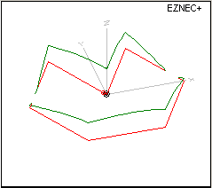
If the current was uniform throughout the elements the calculation would be almost trivial, but we have to take into account that it is sinusoidal, as show in green in the diagram on the right. So the smaller "Y" coordinates at the centre of the driver will have more influence because that's where more current is flowing. By taking small segments of each wire, working out what the current is in the segment and what its "Y" coordinate is, we can calculate an average "current.distance" product for each element. Expressed mathematically:
Centre of Current = [∑x=1→n I(x).Y(x)]/n
We find that the "centre of current" for an "M" shaped element lies at a Y coordinate of 0.34Ymax, and for a "U" shaped element it is 0.65Ymax. Translating these percentages into wavelengths gives an "equivalent boom length" of 0.133λ for the Broadband design and 0.081λ for the Classic design.
It would be quite inappropriate to try to predict Hexbeam performance by looking up Yagi performance figures for these equivalent boom lengths; the situation is much more complex, not least because of the tip coupling which is present in the Hexbeam, but not in a Yagi. However it is interesting to note that:
- These equivalent boom lengths are in the range of values typically used by Yagi designers;
- The use of 0.133λ for a Yagi produces broader F/B performance and a better match to 50Ω than 0.081λ - characteristics similar to those we find in the Hexbeam designs.
I'm not sure the concept of an equivalent boom length has much utility, but the next time I'm asked the question at least I'll have an answer!