Amateur Radio (G3TXQ) - Ten-Tec Corsair II PTO
I love my old ten-tec Corsair II - its performance compares favourably with more modern radios, it's easy to service, and it has “real knobs” for nearly every function; but, arguably, one feature which lets it down is its Permeability Tuned Oscillator (PTO) VFO. I have never had any problem with the frequency stability, but mine have needed the occasional mechanical re-build, and the tuning rate (20kHz per turn) is rather high by modern standards. They can also be rather stiff, or slip, unless they are adjusted carefully.
There are commecially available replacements for the PTO which make use of DDS technology, but none of them is a direct replacement for the Corsair unit. I set out to design and build a DDS replacement which would mimic the PTO functionally as far as possible, and mechanically would be a “drop-in” replacement.
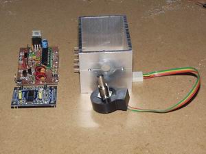
The hardest part of a DDS project for the average Ham is probably soldering in place the tiny DDS chip; I took the easy route and bought a ready-built DDS board available at modest cost on eBay. It comprises an AD9851 chip and 30MHz reference oscillator mounted on a small board together with decoupling capacitors and a low-pass filter (LPF). It's the small blue board in the photos.
The larger hand-wired matrix board (1.7" x 2.2") contains a PIC16F818 controller, RF buffer, low-pass filter, and 5v regulator. The buffer is controlled by the Corsair PTO Enable signal - that makes the DDS replacement suitable for use in the Corsair's external VFO accessory. The DDS board is intended for general purpose use and its LPF has a high cut-off frequency, so I included a second LPF on the matrix board with a much lower cut-off frequency matched to the VFO frequency of 5MHz-5.5MHz. The PIC features a 10-bit A/D converter which reads the Corsair's Offset Tuning voltage and produces a tuning range of approximately +/-2.5kHz.
The optical encoder is a Honeywell/Clarostat 600EN128CBL; it is not cheap, but it is a quality part and is rated for a life of 10 million revolutions. It outputs 128 quadrature pulses per revolution which the PIC firmware decodes as 512 changes of state per revolution; with a DDS frequency step size of 10HZ, that produces a tuning rate of about 5kHz/turn. If the encoder is turned faster than 2 turns per second the PIC firmware increases the tuning rate by a factor ten to 50kHz per turn for fast frequency excursions.
The enclosure is the exact same size as the original PTO and is cut from a length of aluminium section.
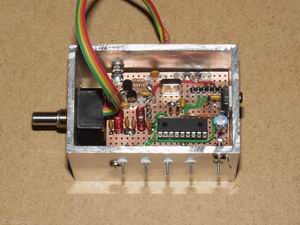
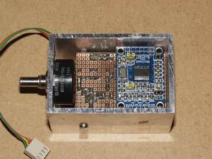
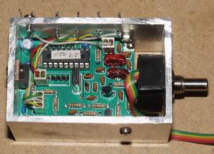
Following photos show the prototype board, DDs module and encoder mounted in the enclosure.
The final photo shows the enclosure containing a board manufactured using
ExpressPCB's MiniBoard
facility. More information is available here:
Controller schematic
PIC object code V1.1 (9/10/2011)
DDS daughter board schematic
Top copper layer
Bottom copper layer
Silk screen layer
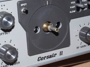
There are a few things to note for anyone copying my design: firstly, the encoder output has Channel A leading Channel B for Counter-Clockwise rotation rather than the more usual Clockwise direction - just reverse the channel connections if your encoder tunes “backwards”; secondly the DDS chip is thirsty and total current consumption is about 150mA - I didn't know if that was something the Corsair 8v regulated supply could cope with so I fed the unit direct from the main 12v supply; lastly, the encoder shaft protrudes only a small distance through the Corsair front panel - I found the knob fitted OK after replacing the original tiny grub screw with something larger.
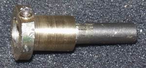
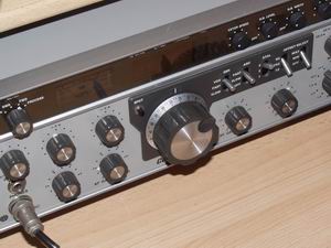
If you prefer not to modify the original Corsair knob, it's perfectly possible to make a shaft extender with stepped diameters which will accept the dial skirt and the knob as shown in the photographs. Externally the Corsair looks un-modified.
