Amateur Radio (G3TXQ) - Tuner Balun: 4:1 or 1:1 ?

Follow the discussions on any Internet Ham Radio forum and it wont be long before someone recommends the use of a 4:1 balun at the output of a tuner feeding a multiband doublet through ladderline. Often the recommendation is accompanied by an explanation such as: “It helps the tuner to tune” or: “It reduces the impedance of the 450 ohm ladderline towards 50Ω”. This article examines whether the ubiquitous advice to use a 4:1 balun in this scenario is valid.
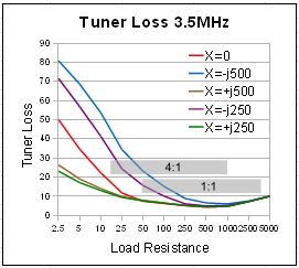
The arguments put forward for a 4:1 impedance transformation often assume that the tuner works best when operating with a load impedance close to 50Ω. That simply isn't true! The chart on the right shows the losses vs load resistance of a typical T-network tuner on 80m for several values of load reactance; 80m was chosen because losses tend to be more evident on the lower-frequency bands. As we can see the lowest tuner losses occur when the load resistance is in the medium/high range 250Ω-2500Ω; the highest losses occur at low load resistances, particularly where they are accompanied by a large capacitive reactance.
Let's now take the example of a commonly proposed multiband doublet - a half-wave 80m dipole fed with 450Ω ladderline. At modest heights above average ground the dipole has a feedpoint impedance close to 50Ω. That means that the impedance seen at the tuner end of the ladderline could have a resistive component anywhere from 50Ω to 4050Ω depending on ladderline length; that range of impedances is indicated by the lower shaded bar in the chart, labelled 1:1. If we now introduce a 4:1 impedance transformation, the range of impedances will be lower by a factor of 4 as indicated by the upper shaded bar labelled 4:1. It's clear that the 1:1 range of impedances will result in the lower overall losses.
In fact, no matter what the antenna impedance, the range of impedances seen at the tuner end of the ladderline would have a “geometric mean” of 450Ω - that is they would swing equally below and above 450Ω, but once we introduce a 4:1 balun the geometric mean will reduce to 112.5Ω. One look at the loss chart tells you that centering the impedances at the higher value is the preferable option.

Let's now take a look at the specific losses that would occur with our example 132 doublet fed with 450Ω ladderline.
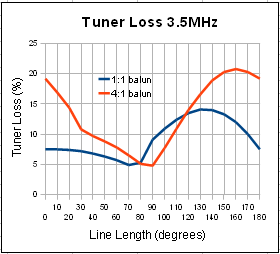
The chart on the right was produced by varying the feedline length from 0° to 180° in 10° steps. At each step the impedance seen by the tuner was calculated both with a 1:1 balun and then with a 4:1 balun, and the tuner losses determined using W9CF's T-network tuner simulator. Of course, beyond 180° the chart simply repeats itself. Ladderline losses were ignored.
Apart from a small range of line lengths between 80° and 115°, where the line has transformed the 50Ω feedpoint impedance to a very high value around 4000Ω, the 1:1 balun is the better option; not only that, the worst case loss never exceeds 14% with the 1:1 balun whereas it reaches 21% with the 4:1 balun.
But what about other bands - the doublet wont be used on just 80m!

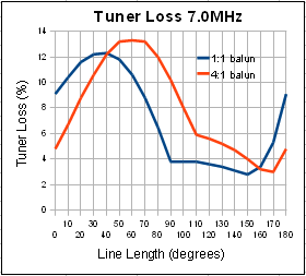
This chart shows the tuner loss plotted against line length for our example doublet on 40m. Here the doublet feedpoint impedance is around 4000Ω, so for short ladderline lengths the 4:1 balun shows an advantage. However, as the ladderline length increases and the impedance is transformed to lower values, the 1:1 balun soon shows the lower losses again. Across the whole range of ladderline lengths the 1:1 balun is twice as likely as the 4:1 to produce lower losses.
The conclusion seems clear: if you have to choose just one balun, unless you know that your combination of doublet/ladderline length falls into the minority of cases where a 4:1 balun has the advantage, a 1:1 balun is the preferred choice. Add into the mix the fact that most 4:1 baluns are Voltage Baluns, whereas to prevent feedline radiation we want balanced currents; then consider that all baluns other than a 1:1 Current Balun have the full transmit voltage applied common-mode across one or more windings, and the case is compelling for a 1:1 Current Balun in this situation.
In this application any small impedance transformation caused by the Current Balun is immaterial because the tuner will compensate, so the windings do not need to be of any specific characteristic impedance. Typically, bifilar windings using Thermaleze wire inserted in Teflon tubes are employed to cope with the high differential-mode voltages present at current minima. Balun specialists "Balun Designs" offer a nice example in their Model 1171.