Amateur Radio (G3TXQ) - What tuners do

Follow the discussions on any Internet Ham Radio forum and it wont be long before someone comments that: "A tuner in the shack can't affect the match at a remote antenna feedpoint", or: "A tuner simply 'fools' the radio into thinking it is matched". On this page we'll look at whether those statements are correct
Firstly we need to understand something about "conjugate matching". I guess most folk are familiar with the "Maximum Power Transfer" theorem which says that if a source has a source resistance of R we can extract the maximum power from it if we provide a load of resistance R. Perhaps less well known is how the theorem applies when the source impedance is a combination of resistance and reactance instead of being purely resistive.
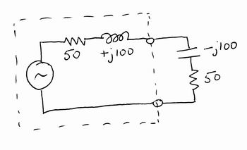
The sketch on the right shows just such a situation, where the source has an impedance of 50+j100. Without working through a complete mathematical proof we can see intuitively that for maximum power transfer the reactance of the source needs to be "cancelled" by an equal-but-opposite reactance in the load, and that the resistive components must still be equal. In other words if the source impedance is R+jX the load impedance needs to be R-jX; we then say that we have a "conjugate match".

Let's see how this works out in a practical antenna system.
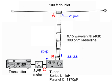
The diagram on the right illustrates a 100ft doublet antenna being centre-fed with 0.15λ of 300Ω ladderline from an L-network tuner. For now, to keep things simple, we'll assume that the ladderline and the tuner have negligible losses.
Let's separate the ladderline from the antenna at point A and connect an analyser across the antenna feedpoint; according to EZNEC we'll measure an impedance of about 26-j420 at a frequency of 3.5MHz. Now reconnect the ladderline to the antenna, but disconnect the other end of the line from the output of the tuner at point B. Connect an analyser across the ladderline terminals and we'll measure an impedance of about 8.8-j2.8 - the ladderline has transformed the antenna feedpoint impedance (26-j420) into something quite different.
It is true that whatever we do with the tuner we cannot affect these two impedances nor, therefore, the VSWR on the ladderline; however the tuner can affect the impedance seen looking into the tuner at point C. A series inductance of 1uH and a shunt capacitance of 1970pF will transform the tuner's 8.8-j2.8 load impedance at point B into 50+j0 at point C - creating the specified load for the transmitter.
So far so good - no surprises!

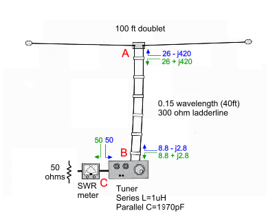
Now let's replace the transmitter with a 50Ω resistor to represent its specified load impedance, and repeat the measurements, but this time measuring the impedances looking back towards the transmitter rather than towards the antenna; in other words we're measuring source impedances rather than load impedances. Oh - and be sure not to alter the tuner settings!
If we disconnect the cable from the input of the tuner and measure the impedance looking back towards the SWR meter, we will of course measure 50+j0 or 50-j0 - they're the same thing. Reconnect the cable.
Now separate the ladderline from the output of the tuner at point B and connect the analyser across the tuner terminals; we'll measure an impedance which is 50Ω modified by the tuner components. In fact we'll measure 8.8+j2.8. Reconnect the ladderline to the output of the tuner.
Now separate the ladderline from the antenna at point A and connect the analyser across the ladderline terminals. The length of ladderline will transform the 8.8+j2.8 impedance we measured previously into a new impedance of 26+j420.
So, to summarise, at points A, B and C we have measured load and source
impedances of:
      A: 26-j420 & 26+j420

      B: 8.8-j2.8 & 8.8+j2.8

      C: 50+j0 & 50-j0
That should look familiar! We observe the interesting result that, at each of the points the tuner has created a conjugate match, ..... even at the remote antenna feedpoint!
At points A & B the tuner can't affect the load impedance, but it can affect the source impedance; conversely at C it can't affect the source impedance but it can affect the load impedance. In fact we could break open the ladderline at any point along its length and we would measure conjugate source and load impedances looking in the two directions.
Another way of looking at the issue is to ask how we are going to easily transfer power into an antenna which has such a high capacitive reactance; after all, a tuner can do nothing about changing that impedance. The answer is that we need to create a source impedance with a similar high inductive reactance. The combined action of the tuner and the ladderline transforms the source impedance of the transmitter into a value that will allow power to flow more readily into the antenna.
Please don't misunderstand - the 300Ω surge impedance of the ladderline is still mis-terminated at the antenna, and it still has a high VSWR on it - the tuner hasn't changed that; but it has changed the steady-state system match at the antenna feedpoint - they are different things!
Also, please note that the source impedance of a typical “real-life” transmitter may be significantly different from 50Ω; however, if the tuner is adjusted to provide a 50Ω load for the transmitter, there will be a conjugate match throughout the system if the transmitter is removed and replaced by a 50Ω resistor across the tuner input terminals.
Lossy systems
So far we have considered the tuner and the ladderline to have negligible losses, which begs
the question: “what happens in a real system with losses?” Let's rework our
example to include losses in the ladderline equivalent to 0.18dB per 100ft, and assume a
tuner inductor Q value of about 100. After re-adjusting the tuner (L=1.06uH and C=1600pF) for
a 50Ω match at its input, we get the following impedances looking towards the antenna:
      A: 26-j420

      B: 12-j1.9

      C: 50+j0
But now, when we place a 50Ω resistor across the input of the tuner and examine the
impedances looking back from the antenna, we get:
      A: 45.7+j421

      B: 12.4+j1.8
Notice that these impedances are no longer the conjugates of those looking in the reverse direction. At the antenna feedpoint (point A) in particular, there is far from a conjugate match. Introducing realistic losses for the ladderline and the tuner has destroyed the “system-wide” conjugate match. There are some special cases where a “system-wide” conjugate match can occur even with a lossy system, but these are probably the exception in typical Amateur Radio installations.
Real-world transmitters
A further question that arises when discussing “system-wide conjugate matches” is whether the transmitter is acting as a Thevenin source, and if so what is its source impedance?
I have performed “load-pull” tests on a number of radios that I own including: two Ten-Tec CorsairIIs, a Ten-Tec OmniVI, and a couple of home-designed QRP transceivers. One of the more extreme results (one of the CorsairIIs on 40m) had the radio producing 20% more power working into a load of 25+/-j21 (SWR(50)=2.4:1) than it did into a 50+j0 load. Does that mean I should adjust the tuner to produce a conjugate match of 25-/+j21 at its input and thereby maximise the power from the radio? No - that would be ill-advised because the radio would not be operating into its specified load impedance, risking increased power dissipation and higher distortion products. Rather, I adjust the tuner for 50+j0 at its input so that the radio sees its specified load; whether or not it also produces a “system-wide” conjugate match - a most unlikely event - is of no concern!
Summary
So what can we say in summary? I believe we can make the following statements:
- The primary function of a tuner is to present the radio with its specified load impedance. To the extent that radios have feelings it could be said that the tuner is “keeping the radio happy”!
- If the radio behaves as a Thevenin source with an impedance equal to its specified load impedance, and if the system is lossless, there will be a conjugate match throughout the system. However, typical radios do not behave in this way, and practical systems are not lossless, so it is extremely unlikely there will be a system-wide conjugate match in a typical Amateur Radio installation.
- In the typical system shown above, the tuner cannot alter the feedpoint impedance of the antenna, lower the SWR on the ladderline, or reduce ladderline losses.
- But making adjustments to the tuner does have some effect throughout the system, including at the antenna; so it is not fair to say that a tuner has an effect only at the radio. However, this should not be interpreted to mean that it is producing a system-wide conjugate match.